


You have 0 items in your cart.

Data logger with 5.7'' color display, with 20 channels, expandable up to 200 ch,2GB on-board memory, USB/LAN PC I/F. 16-bit
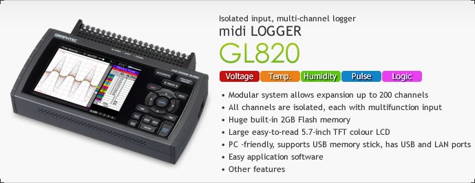
- Modular system allows expansion up to 200 channels
- All channels are isolated, each with multifunction input
- Huge built-in 2GB Flash memory
- Large easy-to-read 5.7-inch TFT colour LCD
- PC -friendly, supports USB memory stick, has USB and LAN ports
Description
|
Huge 2GB Flash Memory, modular system allows expansion up to 200 channels Modular system allows expansion up to 200 channels
All channels are isolated, each with multifunction input
Provides faster sampling rates for voltage measurements. Can achieve 10ms sampling interval when limiting the number of channels in use.
External sampling function Captured data can be synchronized with external timing signals when the external sampling rate function is used.*3 *3: The Logic/alarm cable, (B-513 option), is needed to connect the alarm output ports. Huge built-in 2GB Flash memory Built-in 2GB Flash Memory for reliable long term measurement The 2GB Flash Memory enables secure long term data measurement without using an external storage device. Data is retained even when power is turned off because flash memory is used. Capturing time*4 (20 Analogue channels being used.)
Ring memory function The most recent data is saved when internal memory or external memory is configured in ring memory mode. Captured data size in ring memory mode is limited to 1/3 of available memory. Hot-swappable USB memory sticks Also supports popular USB memory sticks for external storage. The GL820 saves measured data directly to USB memory sticks. USB memory sticks can be replaced during measurement without data loss. Large easy-to-read 5.7-inch wide TFT color LCD Utilises a bright clear 5.7-inch wide TFT color LCD monitor (VGA: 640 x 480 dots). Makes it easy to read data in waveform or digital form and to check your measurement parameter settings. The background color of the screen can be set to black or white.
PC-friendly, supports USB memory stick, has USB and LAN ports Supports USB memory devices Captured data can be saved directly to USB memory sticks when these are chosen for external storage. Easy connection to PC via USB or Ethernet The GL820 can be controlled by a PC if connected by USB cable, allowing transfer of data to a PC in real-time. If you need to move large data files to your PC then the GL820 can emulate an external USB drive for quick data transfer. The WEB & FTP server function, FTP client-server function and NTP client function are supported when the GL820 is connected to the LAN via the Ethernet port. Easy application software Easy connection to PC The GL820 can be controlled by a PC if connected by USB cable, allowing transfer of data to a PC in real-time. If you need to move large data files to your PC then the GL820 can emulate an external USB drive for quick data transfer. Up to 10 units or 500 channels can be connected to 1 PC through LAN or USB. Measurements can be performed simultaneously or independently. Various measurement screens Select from 4 screens such as the Y-T (waveform + digital), Y-T (large waveform), digital view and report view to display measurements in real time.
Three screens are available to view measurements in replay mode. The Y-T (waveform) display, the digital display and the X-Y graph can be selected to show your specified data. The maximum, minimum, average and peak-to-peak values between cursors are shown when using the digital display screen. Simple configuration screens The number of configuration screens has been reduced to five. Parameters can be set easily while viewing measured waveforms. Useful functions Post-process your captured data with useful functions for arithmetic calculation, statistical calculation, search and file format conversion. The configuration of CSV file can be specified. Other features
Alarm warnings can be sent via E-mail when computer is connected to LAN. Can be used with 3 types of power source Chose from AC supply, DC supply or the optional battery pack which enables 6 hours*8 of continuous measurement. The power source is automatically switched to the battery pack when the AC power supply is interupted. If the capacity of the battery pack goes low then measurement is automatically terminated and the captured data file is closed and protected. *8: DC power drive cable and battery pack are optional extras. Measuring time by using the battery pack varies on the conditions. |
||||||||||||||||||||||||||||||||||||||||||||||||||||||||||||||||||||||||||||||||||||||||||||||||||||||||||||||||||||||||||||||||||
In The Box
- AC Adapter - 100 to 240 V AC, 50/60 Hz (with specified type of power cord)
- CD-ROM - User's manual (PDF format), application software
- Quick Start Guide
Manuals/Guides
Spec Sheets
- Graphtec GL820 Isolated Input, Multi-Channel logger Midi Logger Data Sheet
Comparison
- Graphtec GL100 vs GL220 vs GL820 Selection Chart
Other
- Software
- GL820 Application Examples
Manufacturer Specs
|
Item |
Description |
|
|
Number of analog input channels |
20 ch, Expandable up to 200 ch by unit of 20 ch |
|
|
External input output |
Input *1 |
Trigger or Sampling input 1ch, Logic or Pulse input 4 ch |
|
Output *1 |
Alarm output 4 ch |
|
|
Sampling interval |
10 ms to 1 h (in 10 ms to 50 ms, voltage only and limited channel), External |
|
|
Time scale |
1 sec to 24 hour/division |
|
|
Trigger function |
Action |
Start or stop capturing data by the trigger |
|
Source |
Start: Off, Input signal, Alarm, External *1, Clock, Week or Time |
|
|
Combination |
OR or AND condition at the level of signal or edge of signal |
|
|
Condition |
Analog: Rising, Falling, Window-in, Window-out |
|
|
Alarm function |
Detecting method |
Level or edge of signal |
|
Condition |
Analog: Rising, Falling, Window-in, Window-out |
|
|
Alarm output *1 |
4 channels, Output type: Open collector (pulled-up to 5 V by resistor 10 kΩ) |
|
|
Pulse input function *1 |
Accumulating count mode |
Accumulating the number of pulses from the start of measurement |
|
Instant count mode |
Counting the number of pulses per sampling interval |
|
|
Rotation count (RPM) mode |
Counting the number of pulses per second and then it is converted to RPM |
|
|
Max. input pulse rate |
50k pulses/sec or 50k counts per sampling interval (16 bits counter is used) |
|
|
Calculation function |
Between channels |
Addition, Subtraction, Multiplication and Division for analog input |
|
Statistical |
Select two calculations from Average, Peak, Max., Min., RMS |
|
|
Search function |
Search for analog signal levels, values of logic or pulse or alarm point in captured data |
|
|
Interface to PC |
Ethernet (10 BASE-T/100 BASE-TX), USB (Full speed) |
|
|
Storage device |
Built-in Flash memory (2 giga-bytes), USB memory device *2 |
|
|
Data saving function |
Captured data |
Direct saving of data into built-in Flash memory or USB memory device |
|
Others |
Setting conditions, Screen copy |
|
|
Ring capturing mode |
Function: ON/OFF, Number of capturing point: 1000 to 2000000 (size of the capture data will be limited to 1/3 of available memory when in Ring Mode) |
|
|
USB memory device emulation |
USB Memory emulation mode (Transfer or delete the file in built-in memory) |
|
|
Engineering scale function |
Set based on the reference point of the scaled output and input signal for each channel (Voltage measurement: four points are necessary to scale the output, Temperature measurement: two points are necessary to scale the output). |
|
|
Display |
Size |
5.7 inch TFT color LCD (VGA: 640 x 480 dots) |
|
Formats |
Waveform + Digital, Waveform only, Calculation + Digital, Expanded digital |
|
|
Operating environment |
0 °C to 45°C, 5 % to 85 % RH |
|
|
Power source |
AC adapter (100 V to 240 V, 50/60 Hz) |
|
|
Power consumption |
32VA or lower |
|
|
External dimensions (WxDxH) |
approx. 232 x 152 x 50 mm |
|
|
Weight |
approx. 900 g (Excluding AC adapter and battery pack) |
|
Software specifications
|
Item |
Description |
|
Supported OS |
Windows XP / Vista / 7 (32 bits and 64 bits edition) |
|
Functions |
Control GL820, Real-time data capture, Replay data, Data format conversion |
|
GL820 setting control |
Input settings, Memory settings, Alarm settings, Trigger settings |
|
Controlled units |
Up to 10 units or 500 channels |
|
Captured data |
Transfers data in real-time (in binary or CSV format), saved data in GL820 or the USB memory |
|
Displayed information |
Analog waveforms, Logic waveforms, Pulse waveforms, Digital values |
|
Display modes |
Y-T waveforms, Digital values, Report, X-Y graph (specified period of data, data reply only) |
|
Warning functions |
Sends E-mail to the specified address when the alarms occur |
|
File format conversions |
Converts the specified period data or all data to the CSV format (thinning function is available) |
|
Report functions |
Creates the daily or monthly report automatically (can also export directly to Excel) |
GL820 Input Terminal Unit Specifications
|
Item |
Description |
Quantity |
|
AC adapter |
100 V to 240 V AC, 50/60 Hz (with specified type of power cord) |
1set |
|
CD-ROM |
User's manual (PDF format), Application software |
1piece |
|
Quick Start Guide |
|
1copy |
GL820 Input Terminal Unit Specifications
|
Type of input terminal |
Screw terminal (M3 screw) |
||||
|
Method |
Scans by the photo-MOS-relay, all channels isolated, balanced input |
||||
|
Measurment Range |
Voltage |
20, 50, 100, 200, 500 mV, 1, 2, 5, 10, 20, 50V, 1-5 V F.S |
|||
|
Temperature |
Thermocouple : K, J, E, T, R, S, B, N, W (WRe5-26) |
||||
|
Humidity |
0 to 100 % (using humidity sensor (B-530 optional), power is supplied to only one sensor) |
||||
|
Input filter |
Off, 2, 5, 10, 20, 40 (Moving average) |
||||
|
Measurement accuracy *4 |
Voltage |
± 0.1 % of F.S. |
|||
|
Temperature |
Thermocouple |
Measurement range |
Accuracy |
||
|
R/S |
0 ≤ TS ≤100 °C |
± 5.2 °C |
|||
|
100 < TS ≤300 °C |
± 3.0 °C |
||||
|
R : 300 < TS ≤1600 °C |
± (0.05 % of rdg + 2.0 °C) |
||||
|
S : 300 < TS ≤1760 °C |
± (0.05 % of rdg + 2.0 °C) |
||||
|
B |
400 ≤ TS ≤ 600 °C |
± 3.5 °C |
|||
|
600 < TS ≤ 1820 °C |
± (0.05 % of rdg + 2.0 °C) |
||||
|
K |
-200 ≤ TS ≤-100 °C |
± (0.05 % of rdg + 2.0 °C) |
|||
|
-100 < TS ≤1370 °C |
± (0.05 % of rdg + 1.0 °C) |
||||
|
E |
-200 ≤ TS ≤-100 °C |
± (0.05 % of rdg + 2.0 °C) |
|||
|
-100 < TS ≤820 °C |
± (0.05 % of rdg + 1.0 °C) |
||||
|
T |
-200 ≤ TS ≤ -100 °C |
± (0.1 % of rdg + 1.5 °C) |
|||
|
-100 < TS ≤400 °C |
± (0.1 % of rdg + 0.5 °C) |
||||
|
J |
-200 ≤ TS ≤ -100 °C |
± 2.7 °C |
|||
|
-100 ≤ TS ≤100 °C |
± 1.7 °C |
||||
|
100 < TS ≤1100 °C |
± (0.05 % of rdg + 1.0 °C) |
||||
|
N |
0 ≤ TS ≤1300 °C |
± (0.1 % of rdg + 1.0 °C) |
|||
|
W |
0 ≤ TS ≤2315 °C |
± (0.1 % of rdg + 1.5 °C) |
|||
|
Reference Junction Compensation (R.J.C.): ±0.5 °C |
|||||
|
RTD |
Pt100 |
-200 to 850 °C (FS = 1050 °C) |
± 1.0 °C |
||
|
JPt100 |
-200 to 500 °C (FS = 700 °C) |
± 0.8 °C |
|||
|
Pt1000 |
-200 to 500 °C (FS = 700 °C) |
± 0.8 °C |
|||
|
A/D converter |
16 bit (effective resolution: 1/40000 of measuring full range) |
||||
|
Maximum input voltage |
Between +/- terminal |
60 Vp-p |
|||
|
Between channels |
60 Vp-p |
||||
|
Between channels / GND |
60 Vp-p |
||||
|
Maximum input voltage |
Between channels |
350 Vp-p (1minute) |
|||
|
Between channels(-) / GND |
350 Vp-p (1minute) |
||||
|
*1 Logic alarm cable (B-513) option is required. Input signal of External sampling, Logic, Pulse; Maximum voltage: 24 V, Threshold: approx. 2.5 V, Hysteresis: approx. 0.5 V |
|
*2 Size of the USB memory device is unlimited. Maximum file size is limited to 2 GB |
|
*3 DC drive cable (B-514) or battery pack (B-517) option is required. |
|
Subject to the following conditions; |
Tech Specs
|
Dataloggers / Data Acquisition/Data Recorders Template |
|
|
Type (Recorders) |
Data Logger |
|
Style (Recorders) |
Behind Panel / DIN Rail Mount, Bench / Portable |
|
# Channels Expanded plus Logic (Recorders) |
200 EA |
|
# Channels Base Unit (Recorders) |
20 EA |
|
Display (Recorders) |
Built-in, Included w/ Base Unit |
|
# Logic / Digital Channels (Recorders) |
4 |
|
Sampling Interval (Controllers/Recorders) |
10 ms |
|
Sampling Frequency (Recorders) |
100 S/s (0.0001 MS/S) |
|
Input Types (Controllers/Recorders) |
Digital / Logic / On-Off, Frequency / Pulse, T/C - RTD, Voltage |
|
Output Types (Controllers/Recorders) |
Logic / SSR |
|
Bits |
16 |
|
Power Source |
AC Line, Battery, DC Line |
|
Screen Size |
5.7 IN |
|
Special Functions (Recorders) |
External Trigger, Logic / Ladder / Math, PC Software Available, Software / Visible Alarms |
|
Data storage |
Yes |
|
# Data Points |
2000000 |
|
Isolated Inputs (Recorders) |
Yes |
|
Test Equipment General Attributes |
|
|
Unique Features |
Compact Data Acquisition Data LOGGER with modern conveniences such as Ethernet and USB 2.0 interfaces, along with a USB flash memory port. Expandable to 200 channels |
|
Warranty |
12 MONTHS (1 YEARS) |
|
Safety Approval |
CE |
|
Interfaces I/O |
LAN / Ethernet, Analog Input , USB |
|
Storage |
Internal Memory, USB Flash Drive |
|
Product Weight |
2.0 LBS |
|
Product Height |
5 IN |
|
Product Length |
23.2 IN |
|
Product Width |
15.2 IN |
|
Shipping Weight |
4.0 LBS |
|
Data Logging |
Yes |
|
ECCN Number |
EAR99 |
|
Calibration Included |
Factory Calibration |
|
Battery Type |
Li-ion |
|
Power Supply Voltage |
120V/220V Universal |
|
Country of Origin |
Japan |
|
Shipping Height |
16.5 CM (6.50 IN) |
|
Shipping Length |
32.5 CM (12.80 IN) |
|
Shipping Width |
24.5 CM (9.65 IN) |